
Setting Up Portable Generators and Transformers for Entertainment Electrical Systems
Entertainment productions operate in locations that range from fully wired theatrical venues to open fields with no utility power. Portable generators provide that power when utility service is not available or is insufficient. Transformers adapt voltage, isolate circuits, and condition power for sensitive equipment. Setting up generators and transformers correctly — including the grounding system — is a critical Domain 1C skill that the ETCP exam tests directly.
Generator Types for Entertainment
Entertainment-grade portable generators differ substantially from consumer or construction generators:
Touring production generators (trailer-mounted diesel units) are typically rated from 200 kVA to 2,000 kVA and produce three-phase 120/208V or 120/240V power with built-in automatic voltage regulation (AVR). AVR maintains output voltage within ±2–3% regardless of load variation, which is essential for dimmer systems where voltage sag causes output intensity variation. These units include built-in transfer switching, output metering, and Camlok or PowerLok output connections (NFPA, 2023).
Paralleled generators combine two or more generators to serve loads larger than any single unit. Paralleling requires synchronization of voltage, frequency, and phase angle between units before connecting them to a common bus. This is performed by the generator operator using the built-in synchronizing systems — never attempt to parallel generators manually. A paralleling error produces a severe fault current that can destroy both generators and the feeder system.
Inverter generators (smaller, quieter units) use an internal combustion engine to drive an alternator producing variable-frequency AC, which is then rectified to DC and inverted back to clean 60Hz AC. They produce lower harmonic distortion than traditional generators and are quieter at partial loads, making them suitable for locations near audience or sensitive locations. They are typically limited to smaller loads (up to about 10 kW per unit).
Generator Setup Procedure
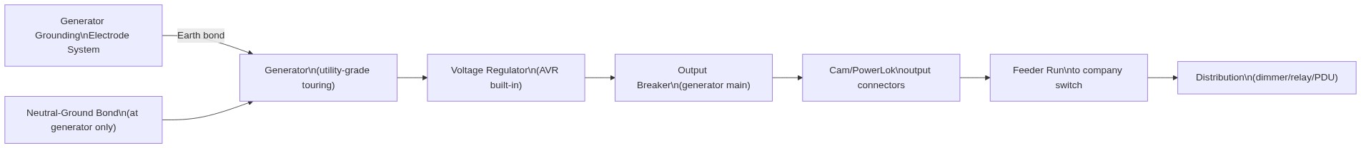
- Position for safety: Generator exhaust must not enter any occupied structure. Position downwind and at least 20 feet from any building opening, door, or window. CO (carbon monoxide) from engine exhaust is odorless and lethal (Occupational Safety and Health Administration [OSHA], 2015).
- Establish the grounding electrode system: NEC 250.34 requires that a generator supplying power to a separately derived system be grounded through a grounding electrode. Drive ground rods at the generator location; connect with appropriately sized grounding electrode conductor (GEC). A separately derived generator system bonds the neutral to the grounding electrode at the generator — not at the distribution equipment downstream.
- Run and connect the output feeder using proper single-pole connector sequence (ground, neutral, phases) with the generator output breaker open (off).
- Start and stabilize: Run the generator at no load for 5–10 minutes, verifying stable voltage and frequency on the output meters before connecting any load.
- Connect loads progressively: Bring distribution equipment online one section at a time. Monitor generator output voltage and frequency; excessive voltage sag or frequency drop under load indicates the generator is approaching its capacity.
Neutral-Ground Bonding and Separately Derived Systems
The most commonly misunderstood aspect of generator grounding is the neutral-ground bond location. The NEC requires that the neutral-to-ground bond for a separately derived system occur at the source — the generator — not at the distribution equipment. When a generator is used as a separately derived system (the default for most standalone generator applications), the distribution equipment downstream must have the neutral-ground bond link removed or opened. Running with a neutral-ground bond at both the generator and the distribution panel creates multiple ground reference points, which can cause equipotential differences between connected equipment and interfere with ground fault detection (National Fire Protection Association [NFPA], 2023).
Transformer Setup
| Transformer Type | Primary Use | Key Setup Consideration |
|---|---|---|
| Step-down (480V to 120/208V) | Venues with 480V service; international touring in 240V territories | Verify turns ratio; delta or wye secondary determines neutral availability |
| Isolation transformer | Eliminate ground loops in audio; reduce noise in sensitive equipment | Secondary neutral-ground bond at transformer secondary, not at source |
| Autotransformer (buck-boost) | Correct 208V to 120V; voltage boost for long feeder runs | Not an isolating device; neutral carries current in delta configurations |
| K-rated transformer | Circuits with high harmonic content (LED walls, VFDs, UPS systems) | K-factor must equal or exceed the calculated K-factor of the connected loads |
When a transformer creates a separately derived system (an isolation transformer or a step-down transformer with a new neutral), the neutral-ground bond must be established at the transformer secondary, not at the primary source. The primary source’s neutral-ground bond remains in place; the transformer secondary has its own bond at the secondary terminals. This creates a clean, properly referenced secondary system without multiple ground references (NFPA, 2023).
K-rated transformers are required when feeding loads with high harmonic content. LEDs, switching power supplies, VFDs, and UPS systems all generate harmonic currents that cause extra heating in standard transformer iron cores. A K-rated transformer is designed with a lower-loss core and oversized neutral conductor to handle this harmonic content. The K-factor of the transformer must equal or exceed the calculated K-factor of the connected loads.
Generator Load Management
Generator capacity management is the entertainment electrician’s responsibility during the show. Monitor generator output on the generator’s meters, watching for:
- Output voltage sag below −5% of nominal when lighting cues fire — indicates the generator is undersized for the load
- Frequency dropping below 59 Hz under load — also indicates overload
- Phase imbalance greater than 10% between phases — indicates uneven load distribution that should be corrected by redistributing loads
- Generator operating above 80% of rated kVA continuously — plan for either load reduction or a larger generator for the next event (NFPA, 2023)
References
Entertainment Technician Certification Program. (2023). Entertainment electrician examination content outline. ESTA.
National Fire Protection Association. (2023). NFPA 70: National Electrical Code, Article 520 — Theaters, Audience Areas of Motion Picture and Television Studios, Performance Areas, and Similar Locations. NFPA.
National Fire Protection Association. (2021). NFPA 70E: Standard for electrical safety in the workplace. NFPA.
Occupational Safety and Health Administration. (2015). 29 CFR 1910.303: General requirements — electrical. U.S. Department of Labor.
Occupational Safety and Health Administration. (2015). 29 CFR 1910.305: Wiring methods, components, and equipment for general use. U.S. Department of Labor.