
Portable Power Feeder Cables for Entertainment: Sizing, Camlok Connectors, and Connection Safety
Portable power feeder cables are the high-current arteries of an entertainment electrical system. They carry hundreds of amperes from the venue’s service connection or generator to dimmer racks, relay racks, and power distribution units. Correct feeder sizing, proper connector use, and a strict connection sequence are all tested in ETCP Domain 1E — and all are matters of safety as well as exam content.
Cable Types for Entertainment Feeder Use
Not every large wire is appropriate for entertainment feeder use. The NEC requires that portable power cables be listed for the application. Two types dominate in entertainment:
- Type W (portable power cable): Designed specifically for rugged, frequent portable use. Heavy rubber insulation on individual conductors plus a heavy rubber jacket. Rated for outdoor and indoor use, resistant to oil, sunlight, and ozone. This is the preferred type for touring production feeder cable because it withstands repeated coiling, uncoiling, loading over, and outdoor exposure.
- Type SOOW: Similar to Type W but also oil-resistant on both the conductor insulation and the jacket. Rated 600V. Common in sizes up to about 2/0 AWG; heavier gauges tend to be Type W.
Tray cable (Type TC) is sometimes used for permanent or semi-permanent entertainment installations but is not appropriate for frequently portable use where the cable is subject to physical abuse (National Fire Protection Association [NFPA], 2023).
Conductor Sizing
Feeder conductors are sized by two criteria: ampacity and voltage drop. The conductor must have an ampacity at or above the calculated load, using NEC Table 310.16 (copper, in conduit) or 310.17 (copper, in free air). Type W cable in free air has higher ampacity than the same gauge in conduit, because open air dissipates heat more effectively.
| Conductor Size | Ampacity (75°C, copper, conduit) | Typical Entertainment Use |
|---|---|---|
| 2 AWG | 130A | Sub-feeds from PDU to smaller distros |
| 1/0 AWG | 170A | Medium feeder runs to dimmer racks |
| 2/0 AWG | 195A | Standard touring dimmer rack feeder |
| 3/0 AWG | 225A | Larger touring dimmer racks |
| 4/0 AWG | 260A | High-current touring, arena main feeds |
| 350 MCM | 350A | Large arena sub-feed |
| 500 MCM | 430A | High-capacity main distribution |
A diversity factor is applied in entertainment: a 96-circuit dimmer rack with 2.4 kW per circuit has a theoretical maximum load of 230.4 kW, but at typical lighting levels only 40–60% of circuits are at full intensity simultaneously. Using 50% diversity, the actual feeder load is approximately 115 kW, reducing the required conductor size significantly. However, if the production is computationally verified to use a high percentage of circuits at full output simultaneously, a higher diversity factor must be used (Cadena, 2009).
Voltage drop: For feeder runs over 100 feet, calculate voltage drop using Vdrop = (2 × K × I × L) / A where K = 12.9 for copper, I = amps, L = one-way length in feet, A = circular mils. A 3% maximum voltage drop is the NEC recommendation for feeders (NFPA, 2023).
Camlok and PowerLok Connectors
Single-pole locking connectors rated at 400A or higher are the standard termination for entertainment feeder cable. Camlok (manufactured by Leviton) and PowerLok (manufactured by Hubbell) are the two dominant brands, and the connectors are electrically and physically interchangeable between brands.
Each connector body is color-coded to prevent mis-connection:
- Black = Phase A
- Red = Phase B
- Blue = Phase C
- White = Neutral
- Green = Equipment ground
After inserting the connector into its receptacle, the cam collar must be rotated to the locked position. An incompletely locked connector will arc under the high current of a feeder connection, instantly carbonizing the contact surfaces and destroying the connector. Before applying power, verify every connector is locked with a firm pull test.

Connection Sequence: Safety Critical
The sequence for connecting and disconnecting feeder cables is not optional — it is a fundamental electrical safety practice. Connecting in the wrong sequence can energize exposed connector pins or create dangerous voltage differentials between equipment.
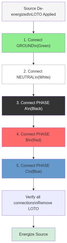
Disconnect in the opposite order
The disconnect sequence is the reverse: de-energize the source, lock it out, then disconnect Phase C, Phase B, Phase A, Neutral, and finally Ground. The ground is always the last conductor disconnected, ensuring that equipment grounding is maintained as long as any possibility of energization exists (Occupational Safety and Health Administration [OSHA], 2015).
Testing Feeder Assemblies
Every feeder assembly should be tested before first use and periodically thereafter:
- Continuity test: Use a multimeter to verify continuity from each source connector to the matching load connector. Confirm there are no shorts between phases or between phase and ground.
- Insulation resistance test (Megger): A megohmmeter applies 500V or 1000V DC to the conductors and measures the resistance of the insulation to ground. A healthy cable insulation reads in the megohm range. Values below 1 megohm indicate compromised insulation that must be investigated before the cable is put in service. Insulation failures from crush damage, UV degradation, or chemical exposure will not be visible during a visual inspection (Cadena, 2009).
References
Cadena, R. (2009). Electricity for the entertainment electrician & technician. Focal Press.
Entertainment Technician Certification Program. (2023). Entertainment electrician examination content outline. ESTA.
National Fire Protection Association. (2023). NFPA 70: National Electrical Code. NFPA.
Occupational Safety and Health Administration. (2015). 29 CFR 1910.303: General requirements for electrical installations. U.S. Department of Labor.