
Multi-Cable Systems and 19-Pin Socapex Connectors for Entertainment Lighting
Multi-cable systems exist to solve a cable management problem: a fully loaded batten or lighting position may require 20, 30, or 48 individual circuits, each needing its own cable from the distribution point. Running that many individual cables is slow, heavy, and creates a management nightmare. Multi-cable bundles multiple circuits into a single assembly with a multi-pin connector, dramatically reducing the number of cables hanging from a lighting position while maintaining individual circuit control.
The Socapex Standard
The 19-pin circular connector manufactured by Socapex (now part of Amphenol) became the North American entertainment industry standard for multi-cable systems carrying six circuits. The connector shell is approximately 55mm in diameter, with 19 pins arranged in a circular pattern. All six circuits in the connector share a common design: each circuit has a dedicated hot pin and neutral pin, plus one of six ground pins. A 19th pin provides chassis bonding between the connector bodies themselves (Cadena, 2009).
The 19-pin Socapex carries six independent 20A circuits — six hots, six neutrals, and seven ground conductors — in a connector that can be made and broken in seconds. The cable itself typically contains 12 AWG conductors (rated to 20A) with each conductor individually insulated, all wrapped in a common jacket. Common lengths in entertainment rental inventory are 25 feet, 50 feet, and 100 feet.
19-Pin Pinout
| Circuit | Hot Pin | Neutral Pin | Ground Pin |
|---|---|---|---|
| Circuit 1 | 1 | 2 | 7 |
| Circuit 2 | 3 | 4 | 8 |
| Circuit 3 | 5 | 6 | 9 |
| Circuit 4 | 10 | 11 | 15 |
| Circuit 5 | 12 | 13 | 16 |
| Circuit 6 | 14 | 17 | 18 |
| Chassis ground | Pin 19 (connector shell bonding) | ||
Note that each of the six circuits has its own dedicated ground pin — this is a design requirement for entertainment multi-cable, ensuring that a fault in any one circuit clears through a direct ground path and does not affect other circuits. The 19th pin (chassis) bonds the connector body to the cable shield if present.

How Multi-Cable Systems Work
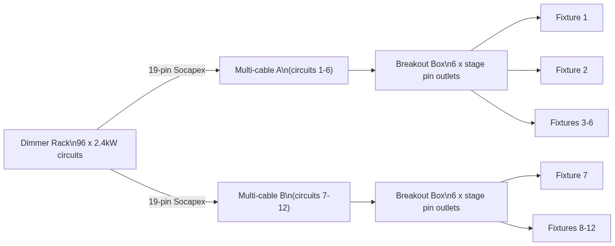
At the dimmer rack end, a multi-cable assembly connects to a group of six dimmer outputs through a panel-mounted 19-pin female connector. The multi-cable runs from the rack position to the lighting position — typically along a batten, truss, or through a cable drop. At the fixture end, a breakout box separates the 19-pin connector back into six individual stage pin outlets. Luminaires connect to the stage pin outlets using individual branch circuit cable (Cadena, 2009).
Breakout box types:
- Through (pass-through) breakout boxes: Have a 19-pin female input and a 19-pin male output (called a THRU port) in addition to the six branch circuit outlets. This allows additional breakout boxes to be daisy-chained from the same multi-cable assembly, extending circuits further along the position.
- Terminating breakout boxes: Have only the 19-pin female input and the six outlets — no THRU port. Used at the end of a multi-cable chain.
Wiring Verification and Testing
Every multi-cable assembly must be verified before use. The primary concern is polarity — a wiring error that swaps hot and neutral in one circuit creates a reverse-polarity condition: the load side of the dimmer (the controlled conductor) is the neutral rather than the hot. This means that even when the circuit is dimmed to zero, the fixture’s lamp socket may be energized to line voltage at the shell of the socket, creating a shock hazard for anyone changing a lamp (Cadena, 2009).
Testing procedure:
- Connect the multi-cable assembly between a power source (energized to a known circuit) and a breakout box.
- At each breakout outlet, use a receptacle tester or voltmeter to verify correct polarity (hot on the correct blade, neutral on the correct blade, ground present).
- Verify all six circuits are continuous and none are shorted to each other or to ground.
- A non-contact voltage tester at the hot blade of each outlet should indicate voltage; the neutral and ground blades should indicate no voltage.
A new or unfamiliar multi-cable assembly should always be tested before being placed in a lighting rig. Reverse polarity in a multi-cable is not immediately obvious during normal operation — fixtures work normally — but creates a real hazard during re-lamping.
Common Failure Modes
- Bent or damaged pins: The 19-pin connector body must be inspected before each use. A bent pin may not make contact, producing a dead circuit. A pin pushed back into the connector body indicates internal damage to the contact retention clip.
- Broken internal conductors: Flexion fatigue from repeated coiling and uncoiling eventually breaks individual conductors, typically at the connector entry point where movement is greatest.
- Contaminated contacts: Outdoor use in rain or dust can contaminate pin contacts, causing intermittent connections. Clean with contact cleaner specified for electronic connectors.
References
Cadena, R. (2009). Electricity for the entertainment electrician & technician. Focal Press.
National Fire Protection Association. (2023). NFPA 70: National Electrical Code. NFPA.
See Also:
- Multi-Cable Systems and 19-Pin Socapex Connectors for Entertainment Lighting
- ETCP Electrician Exam 1D: Setting Up Entertainment Lighting Control Systems
- Entertainment Power Connectors: Stage Pin, Edison, Twist-Lock, Camlok, and IEC 60309
- Entertainment Power Connectors: Stage Pin, Edison, Twist-Lock, Camlok, and IEC 60309