
Feeder Wiring for Entertainment Electrical Systems: Single-Pole Connectors and Bare-End Connections
Feeder wiring carries the bulk power from the venue’s service or generator to the production’s distribution equipment. Feeders operate at currents of 200A to 600A per phase — high enough that a single mistake can cause fire, severe arc flash, or death. Domain 1C of the ETCP exam tests feeder wiring knowledge thoroughly, covering both single-pole locking connector systems and bare-end connections to bus lugs.
What Is a Feeder?
A feeder is the circuit conductors between the service equipment (or the source of a separately derived system) and the final branch-circuit overcurrent device. In entertainment, feeders connect the venue’s company switch (or generator output) to the dimmer rack, relay rack, or PDU. Feeders carry all the current for every load downstream — if a 96-circuit dimmer rack is loaded to 50% of its capacity, the feeder must be sized for the total load of all loaded circuits simultaneously (National Fire Protection Association [NFPA], 2023).
Single-Pole Locking Connectors (Camlok / PowerLok)
Single-pole locking connectors are the standard termination for portable entertainment feeder cable. Each connector carries one conductor; a complete three-phase four-wire-plus-ground feeder set consists of five connectors: black (Phase A), red (Phase B), blue (Phase C), white (neutral), and green (ground).
The locking mechanism consists of a cam collar on the female connector (receptacle) that rotates over a lug on the male connector (plug), creating a mechanical lock that prevents disconnection under load. After inserting each connector, rotate the cam collar to the fully locked position and confirm with a firm pull test — a connector that pulls out before the cam is fully locked is not connected (NFPA, 2023).
Gender convention: Female connectors (receptacles) are typically used on the source or panel side; male connectors (plugs) on the cable end. This convention ensures that when the cable is disconnected from the source, the energized connectors are female (recessed contacts), not male (exposed pins). This is a safety design.
The Connection Sequence
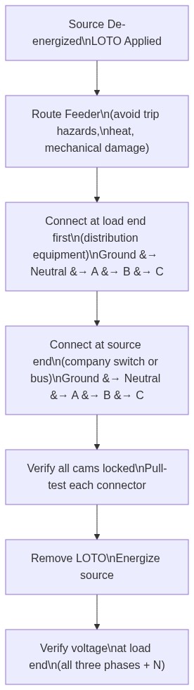
The connection sequence — ground first, neutral second, phases last — is non-negotiable. The ground must be established before any current-carrying conductor is connected, so that any fault current has a path to ground the instant it occurs. The neutral is connected before phases because connecting a phase conductor before neutral in a three-phase system can cause a voltage transient across the neutral-ground bonding system that damages connected equipment.
Connecting at the load end (the distribution equipment) before the source end ensures that if the source is accidentally energized before the connection is complete, the current path ends at the distribution equipment’s open input breaker — not in an open Camlok connector being handled by a technician.
The disconnect sequence is strictly the reverse: de-energize and lock out the source, then disconnect in the order Phase C, Phase B, Phase A, Neutral, Ground (OSHA, 2015).
Bare-End Connections to Bus Lugs
Some venue company switches and generator output panels use lug-type connections (bare conductor lugs) rather than Camlok connectors. Bare-end connections require additional care because the work involves exposed bare conductors at the connection point:
| Step | Bare-End Connection Procedure |
|---|---|
| 1 | Verify source is de-energized and locked out before any work |
| 2 | Strip conductor insulation — expose only the length needed for the lug connection (typically 3/4 to 1 inch) |
| 3 | Insert bare conductor into lug; tighten to manufacturer torque specification |
| 4 | Cover any exposed bare conductor beyond the lug with listed electrical tape or heat-shrink tubing |
| 5 | Verify all five conductors (A, B, C, N, G) are connected before energizing |
| 6 | Ensure no bare conductor is accessible after connection — if bare copper is reachable, the connection is not complete |
Bare-end connections to bus lugs must be made with the source locked out. There is no equivalent of the Camlok’s gender convention that protects a bare end — once the insulation is stripped, the conductor is exposed. Personnel working on bare-end connections must use appropriate PPE for the arc flash hazard category of the equipment being worked on, determined by an arc flash hazard analysis per NFPA 70E (National Fire Protection Association [NFPA], 2021).
Feeder Routing
Routing a feeder cable through a venue requires planning for three concerns:
- Mechanical protection: Feeder cables must not be subject to physical damage. Cables crossing vehicle paths require rated cable bridges. Cables in high-traffic areas should be routed overhead or in cable trays where possible. Single-pole feeder cable is heavy — 4/0 AWG cable weighs approximately 3 lb per foot — and creates a trip hazard if not managed.
- Bending radius: Large feeder cable has a minimum bending radius, typically 8 times the cable diameter for non-shielded portable power cable. Exceeding the minimum bend radius kinks the cable and damages conductors. Plan feeder routes that allow gradual curves, not sharp corners (NFPA, 2023).
- Length and voltage drop: For feeder runs over 100 feet, calculate voltage drop. A 3% maximum is the NEC recommendation. Undersized feeder cable or excessive run length causes voltage sag that affects dimmer output levels and can cause problems with sensitive equipment.
Verification After Connection
After connecting the feeder and energizing the source:
- Measure phase-to-phase voltage at the distribution equipment input terminals — all three pairs should read within 3% of each other
- Measure phase-to-neutral voltage at each phase — should be within 3% of nominal (120V in a 120/208V system)
- Measure neutral-to-ground voltage — should be near zero; a significant voltage (more than 3–5V) indicates a grounding problem or excessive neutral current (NFPA, 2023)
- Verify phase rotation if three-phase motor loads are connected downstream
References
Entertainment Technician Certification Program. (2023). Entertainment electrician examination content outline. ESTA.
National Fire Protection Association. (2023). NFPA 70: National Electrical Code, Article 520 — Theaters, Audience Areas of Motion Picture and Television Studios, Performance Areas, and Similar Locations. NFPA.
National Fire Protection Association. (2021). NFPA 70E: Standard for electrical safety in the workplace. NFPA.
Occupational Safety and Health Administration. (2015). 29 CFR 1910.303: General requirements — electrical. U.S. Department of Labor.
Occupational Safety and Health Administration. (2015). 29 CFR 1910.305: Wiring methods, components, and equipment for general use. U.S. Department of Labor.